
Cart is empty

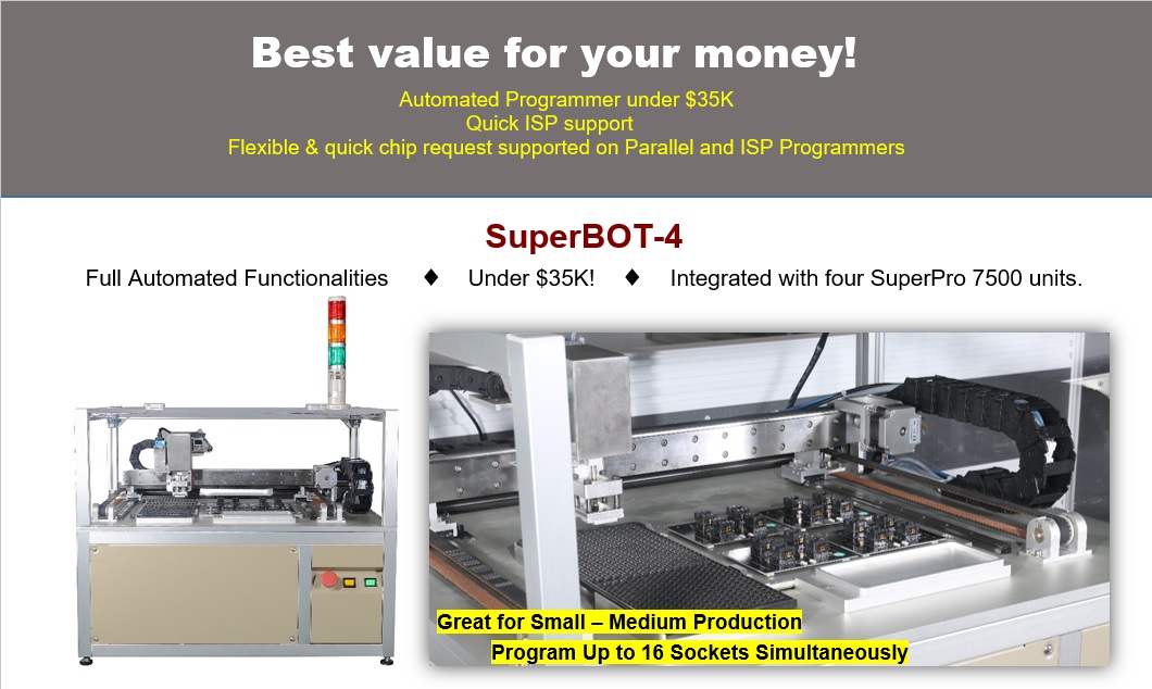

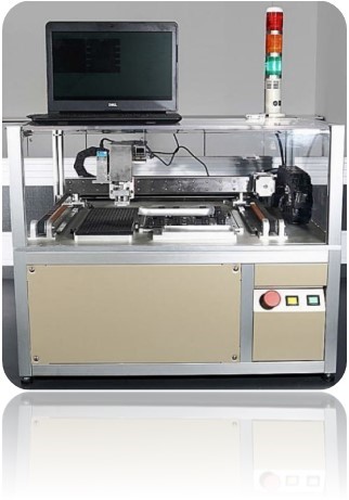
Introducing SuperBOT-4 Desktop Automated IC Programmer
03/10/2016
Introducing SuperBot-4 Desktop Automated IC Programmer
Earn up to $10,000 Commission on an Automated System Referral!*
SuperBOT-4 is designed for small to medium automated programming projects. The device includes a tray with automatic chip pickup and placement for programming sockets. The entire programming procedure is automated, thus replacing traditional manual operations.
I2C Programming Using Xeltek SuperPro IS01 Serial Programmer
03/09/2016
Serial EEPROMs are suitable when a less amount of nonvolatile, read/write memory is needed in a design. These are small and inexpensive which are extremely useful when a minimum number of I/Os are used. There are different kinds of serial EEPROM devices which can be categorized on the basis of communication protocol they use for ISP programming.
– IIC (Inter Integrated Circuit),
– SPI(Serial Peripheral Interface),
– MW (Micro Wire),
– JTAG (Joint Test Action Group).
In this article, we will discuss EEPROM programming through I²C interface using ISP programmers such as Xeltek IS01.
I²C only uses two bidirectional open-drain lines, Serial Data Line (SDA) and Serial Clock (SCL), pulled up with resistors. Typical voltages used are +5 V or +3.3 V although systems with other voltages are also permitted.
The 24C04serial EEPROM supports the I2C protocol. This protocol defines any device that sends data ontothe bus as a transmitter and any device that reads the data as a receiver. The device that controls thedata transfer is known as the master and the other as the slave. The master will always initiate a datatransfer and will provide the serial clock for synchronization. The 24/25x04 are always slavedevices in all communications.
In order to program any serial EEPROM in-circuit, the PCB has to be designed to be able to program serially. The following points should be kept in mind:
1. Serial input, Output, and clock pins must be separated from the rest of the circuit and easily accessible externally. Otherwise, signals may clash and proper programming may not be possible.
2. If the device power pin is separated from the circuit, then the programmer power may be applied to the device. Otherwise, separate power must be applied to the target PCB.
The programming operation steps are as follows:
1. Search for the type of the chip to be operated in the ISP programming software and view the
Device information dialogue box.
2. Connect the signal lines (including GND) for the corresponding interfaces of the ISP
programmer with the target board.
3. If the above “mass production" function is to be used, TPIN and TPOUT signal lines
should also be connected.
4. It is recommended that the power of the target board is supplied independently, especially for the target board with high power consumption and with multiple power systems. If it is confirmed that the power is supplied by the programmer ISP cable, the VPP should be connected.
5. The independent power supplier of the target board switches on the power.
6. Run programming operations such as erase/blank check/ program/ verify.
Apart from dedicated ISP programmer SPIS01, parallel standalone programmers like SP6100 and SP611S can also be used for ISP programming using ISP header connector on Zif48 socket.
For more information, please click the button below or call 408-530-8080.

Using the ATE Port to Control ISP Programmers
03/09/2016
In-system / In-circuit programming (ISP) is the ability of programming an IC chip that is already soldered on the circuit board using serial programming algorithms. In-system programming helps eliminate tedious programming stages prior to assembling the system and reduce multiple tasks to a single production phase.
Since there is no need to desolder an IC chip, code or design changes are more convenient by simply reprogramming the chip already on the printed circuit board (PCB). SuperProIS01 is Xeltek's portable ISP programmer. It supports most ISP protocols like I2C, SPI, UART, BDM, MW, JTAG, CAN, RS232 etc. while also having the ability to operate in stand-alone mode using a secure digital (SD) card. SuperProIS01 comes with an Automated Test Equipment (ATE) interface which allows operating and controlling programmers through external signals.
An ATE control port is used for communication with an external host or integration into the automatic programming / test equipment. Beside using the built-in keyboard, users can also operate SuperProIS01 programmers through the ATE interface. In order to ensure security and accuracy of signals between the two equipments, the ATE interface adopts opto-coupling device to isolate signals. Note that while using the ATE interface, it is required to set the power voltage and appropriate reference voltage point correctly for the external equipment.
ATE Port Pinout:


